Hackaday
Fresh hacks every day
Some projects start as hacks, and end as products — that’s the case for [Akio Sato]’s project Loko, the LoRa/GPS tracker that was entered in our 2025 Pet Hacks Contest. The project dates all the way back to 2019 on Hackaday.io, and through its logs you can see its evolution up to the announcement that Loko is available from SeeedStudio.
It’s not a device necessarily limited to pets. In fact, the original use case appears to have been a backup locator beacon for lost drones. But it’s still a good fit for the contest none-the-less: at 12 grams, the tiny tracking device won’t bother even the most diminutive of pups, and will fit on any collar at only 30 mm x 23 mm. The “ground station” that pairs with your phone is a bit bigger, of course, but unless you have a Newfoundlander or a St. Bernard you’re likely bigger than fido. The devices use LoRa to provide a range up to 15 km — maybe better if you can loop them into a LoRaWAN. Depending on how often you pin the tracker, it can apparently last for as long as 270 days, which we really hope you won’t need to track a missing pet.
The hardware is based around Seeed’s Wio-E5 LoRa chip, which packages an STM32 with a LoRA radio. The firmware is written in MicroPython, and everything is available via GitHub under the MIT license. Though the code for the mobile app that interfaces with that hardware doesn’t appear to be in the repository at the moment. (There are folders, but they’re disappointingly empty.) The apps are available free on the iOS App Store and Google Play, however.
There’s still plenty of time to submit your own hacks to the Pet Hacks Contest, so please do! You have until April 25th, so if you haven’t started yet, it’s not too late to get hacking.
From Blog – Hackaday via this RSS feed
If you work with virtual machines, perhaps to spin up a clean OS install for testing, historically you have either bitten the bullet and used one of the commercial options, or spent time getting your hands dirty with something open source. Over recent years that has changed, with the arrival of open source graphical applications for effortless VM usage. We’ve used GNOME Boxes here to make our lives a lot easier. Now KDE are also joining the party with Karton, a project which will deliver what looks very similar to Boxes in the KDE desktop.
The news comes in a post from Derek Lin, and shows us what work has already been done as well as a roadmap for future work. At the moment it’s in no way production ready and it only works with QEMU, but it can generate new VMs, run them, and capture their screens to a desktop window. Having no wish to join in any Linux desktop holy wars we look forward to seeing this piece of software progress, as it’s a Google Summer Of Code project we hope there will be plenty more to see shortly.
Still using the commercial option? You can move to open source too!
From Blog – Hackaday via this RSS feed
We’re tremendously excited to be able to announce that the Hackaday Supercon is on for 2025, and will be taking place October 31st through November 2nd in Pasadena, California.
Supercon is about bringing the Hackaday community together to share our great ideas, big and small. So get to brainstorming, because we’d like to hear what you’ve been up to! Like last year, we’ll be featuring both longer and shorter talks, and hope to get a great mix of both first-time presenters and Hackaday luminaries. If you know someone you think should give a talk, point them here.
The Call for Participation form is online now, and you’ve got until July 3rd to get yourself signed up.
Honestly, just the people that Supercon brings together is reason enough to attend, but then you throw in the talks, the badge-hacking, the food, and the miscellaneous shenanigans … it’s an event you really don’t want to miss. And as always, presenters get in for free, get their moment in the sun, and get warm vibes from the Hackaday audience. Get yourself signed up now!
We’ll have more news forthcoming in the next few weeks, including the start of ticket sales, so be sure to keep your eyes on Hackaday.
From Blog – Hackaday via this RSS feed
If we asked you to think of a device that converts a chemical reaction into electricity, you’d probably say we were thinking of a battery. That’s true, but there is another device that does this that is both very similar and very different from a battery: the fuel cell.
In a very simple way, you can think of a fuel cell as a battery that consumes the chemicals it uses and allows you to replace those chemicals so that, as long as you have fuel, you can have electricity. However, the truth is a little more complicated than that. Batteries are energy storage devices. They run out when the energy stored in the chemicals runs out. In fact, many batteries can take electricity and reverse the chemical reaction, in effect recharging them. Fuel cells react chemicals to produce electricity. No fuel, no electricity.
Superficially, the two devices seem very similar. Like batteries, fuel cells have an anode and a cathode. They also have an electrolyte, but its purpose isn’t the same as in a conventional battery. Typically, a catalyst causes fuel to oxidize, creating positively charged ions and electrons. These ions move from the anode to the cathode, and the electrons move from the anode, through an external circuit, and then to the cathode, so electric current occurs. As a byproduct, many fuel cells produce potentially useful byproducts like water. NASA has the animation below that shows how one type of cell works.
History
Sir William Grove seems to have made the first fuel cell in 1838, publishing in The London and Edinburgh Philosophical Magazine and Journal of Science. His fuel cell used dilute acid, copper sulphate, along with sheet metal and porcelain. Today, the phosphoric acid fuel cell is similar to Grove’s design.
The Bacon fuel cell is due to Francis Thomas Bacon and uses alkaline fuel. Modern versions of this are in use today by NASA and others. Although Bacon’s fuel cell could produce 5 kW, it was General Electric in 1955 that started creating larger units. GE chemists developed an ion exchange membrane that included a platinum catalyst. Named after the developers, the “Grubb-Niedrach” fuel cell flew in Gemini space capsules. By 1959, a fuel cell tractor prototype was running, as well as a welding machine powered by a Bacon cell.
One of the reasons spacecraft often use fuel cells is that many cells take hydrogen and oxygen as fuel and put out electricity and water. There are already gas tanks available, and you can always use water.
Types of Fuel Cells
Not all fuel cells use the same fuel or produce the same byproducts. At the anode, a catalyst ionizes the fuel, which produces a positive ion and a free electron. The electrolyte, often a membrane, can pass ions, but not the electrons. That way, the ions move towards the cathode, but the electrons have to find another way — through the load — to get to the cathode. When they meet again, a reaction with more fuel and a catalyst produces the byproduct: hydrogen and oxygen form water.
Most common cells use hydrogen and oxygen with an anode catalyst of platinum and a cathode catalyst of nickel. The voltage output per cell is often less than a volt. However, some fuel cells use hydrocarbons. Diesel, methanol, and other hydrocarbons can produce electricity and carbon dioxide as a byproduct, along with water. You can even use some unusual organic inputs, although to be fair, those are microbial fuel cells.
Common types include:
Alkaline – The Bacon cell was a fixture in space capsules, using carbon electrodes, a catalyst, and a hydroxide electrolyte.Solid acid – These use a solid acid material as electrolyte. The material is heated to increase conductivity.Phosphoric acid – Another acid-based technology that operates at hotter temperatures.Molten carbonate – These work at high temperatures using lithium potassium carbonate as an electrolyte.Solid oxide – Another high temperature that uses zirconia ceramic as the electrolyte.
In addition to technology, you can consider some fuel cells as stationary — typically producing a lot of power for consumption by some power grid — or mobile.
Using fuel cells in stationary applications is attractive partly because they have no moving parts. However, you need a way to fuel it and — if you want efficiency — you need a way to harness the waste heat produced. It is possible, for example, to use solar power to turn water into gas and then use that gas to feed a fuel cell. It is possible to use the heat directly or to convert it to electricity in a more conventional way.
Space
Fuel cells have a long history in space. You can see how alkaline Bacon cells were used in early fuel cells in the video below.
Apollo (left) and Shuttle (right) fuel cells (from a NASA briefing)
Very early fuel cells — starting with Gemini in 1962 — used a proton exchange membrane. However, in 1967, NASA started using Nafion from DuPont, which was improved over the old membranes.
However, alkaline cells had vastly improved power density, and from Apollo on, these cells, using a potassium hydroxide electrolyte, were standard issue.
Even the Shuttle had fuel cells. Russian spacecraft also had fuel cells, starting with a liquid oxygen-hydrogen cell used on the Soviet Lunar Orbital Spacecraft (LOK).
The shuttle’s power plant measured 14 x 15 x 45 inches and weighed 260 pounds. They were installed under the payload bay, just aft of the crew compartment. They drew cryogenic gases from nearby tanks and could provide 12 kW continuously, and up to 16 kW. However, they typically were taxed at about 50% capacity. Each orbiter’s power plant contained 96 individual cells connected to achieve a 28-volt output.
Going Mobile
There have been attempts to make fuel cell cars, but with the difficulty of delivering, storing, and transporting hydrogen, there has been resistance. The Toyota Mirai, for example, costs $57,000, yet owners sued because they couldn’t obtain hydrogen. Some buses use fuel cells, and a small number of trains (including the one mentioned in the video below).
Surprisingly, there is a market for forklifts using fuel cells. The clean output makes them ideal for indoor operation. Batteries? They take longer to charge and don’t work well in the cold. Fuel cells don’t mind the cold, and you can top them off in three minutes.
There have been attempts to put fuel cells into any vehicle you can imagine. Airplanes, motorcycles, and boats sporting fuel cells have all made the rounds.
Can You DIY?
We have seen a few fuel cell projects, but they all seem to vanish over time. In theory, it shouldn’t be that hard, unless you demand commercial efficiency. However, it can be done, as you can see in the video below. If you make a fuel cell, be sure to send us a tip so we can spread the word.
Featured image: “SEM micrograph of an MEA cross section” by [Xi Yin]
From Blog – Hackaday via this RSS feed
Plenty of consumer goods, from passenger vehicles to toys to electronics, get tossed out prematurely for all kinds of reasons. Repairable damage, market trends, planned obsolescence, and bad design can all lead to an early sunset on something that might still have some useful life in it. This was certainly the case for a sound system that [Bill] found — despite a set of good speakers, the poor design of the hardware combined with some damage was enough for the owner to toss it. But [Bill] took up the challenge to get it back in working order again.
The main problem with this unit is that of design. It relies on a remote control to turn it on and operate everything, and if that breaks or is lost, the entire unit won’t even power on. Tracing the remote back to the control board reveals a 15-pin connector, and some other audio sleuths online have a few ways of using this port to control the system without the remote.
[Bill] found a few mistakes that needed to be corrected, and was eventually able to get an ESP8266 (and eventually an ESP32) to control the unit thanks largely to the fact that it communicates using a slightly modified I2C protocol.
There were a few pieces of physical damage to correct, too. First, the AC power cable had been cut off which was simple enough to replace, but [Bill] also found that a power connector inside the unit was loose as well. With that taken care of he has a perfectly functional and remarkably inexpensive sound system ready for movies or music. There are some other options available for getting a set of speakers blasting tunes again as well, like building the amplifier for them from scratch from the get-go.
From Blog – Hackaday via this RSS feed
Although there are some ferries and commercial boats that use a multi-hull design, the most recognizable catamarans by far are those used for sailing. They have a number of advantages over monohull boats including higher stability, shallower draft, more deck space, and often less drag. Of course, these advantages aren’t exclusive to sailboats, and plenty of motorized recreational craft are starting to take advantage of this style as well. It’s also fairly straightforward to remove the sails and add powered locomotion as well, as this electric catamaran demonstrates.
Not only is this catamaran electric, but it’s solar powered as well. With the mast removed, the solar panels can be fitted to a canopy which provides 600 watts of power as well as shade to both passengers. The solar panels charge two 12V 100ah LifePo4 batteries and run a pair of motors. That’s another benefit of using a sailing cat as an electric boat platform: the rudders can be removed and a pair of motors installed without any additional drilling in the hulls, and the boat can be steered with differential thrust, although this boat also makes allowances for pointing the motors in different directions as well.
In addition to a highly polished electric drivetrain, the former sailboat adds some creature comforts as well, replacing the trampoline with a pair of seats and adding an electric hoist to raise and lower the canopy. As energy density goes up and costs come down for solar panels, more and more watercraft are taking advantage of this style of propulsion as well. In the past we’ve seen solar kayaks, solar houseboats, and custom-built catamarans (instead of conversions) as well.
From Blog – Hackaday via this RSS feed
DIY mechatronics always has some unique challenges when relying on simple tools. 3D printing enables some great abilities but high precision gearboxes are still a difficult problem for many. Answering this problem, [Sergei Mishin] has developed a very interesting gearbox solution based on a research paper looking into simple rollers instead of traditional gears. The unique attributes of the design come from the ability to have a compact angled gearbox similar to a bevel gearbox.
Multiple rollers rest on a simple shaft allowing each roller to have independent rotation. This is important because having a circular crown gear for angled transmission creates different rotation speeds. In [Sergei]’s testing, he found that his example gearbox could withstand 9 Nm with the actual adapter breaking before the gearbox showing decent strength.
Of course, how does this differ from a normal bevel gear setup or other 3D printed gearboxes? While 3D printed gears have great flexibility in their simplicity to make, having plastic on plastic is generally very difficult to get precise and long lasting. [Sergei]’s design allows for a highly complex crown gear to take advantage of 3D printing while allowing for simple rollers for improved strength and precision.
While claims of “zero backlash” may be a bit far-fetched, this design still shows great potential in helping make some cool projects. Unique gearboxes are somewhat common here at Hackaday such as this wobbly pericyclic gearbox, but they almost always have a fun spin!
Thanks to [M] for the tip!
From Blog – Hackaday via this RSS feed
Regular vs gene-edited spider silk with a fluorescent gene added. (Credit: Santiago-Rivera et al. 2025, Angewandte Chemie)
Continuing the scientific theme of adding fluorescent proteins to everything that moves, this time spiders found themselves at the pointy end of the CRISPR-Cas9 injection needle. In a study by researchers at the University of Bayreuth, common house spiders (Parasteatoda tepidariorum) had a gene inserted for a red fluorescent protein in addition to having an existing gene for eye development disabled. This was the first time that spiders have been subjected to this kind of gene-editing study, mostly due to how fiddly they are to handle as well as their genome duplication characteristics.
In the research paper in Angewandte Chemie the methods and results are detailed, with the knock-out approach of the sine oculis (C1) gene being tried first as a proof of concept. The CRISPR solution was injected into the ovaries of female spiders, whose offspring then carried the mutation. With clear deficiencies in eye development observable in this offspring, the researchers moved on to adding the red fluorescent protein gene with another CRISPR solution, which targets the major ampullate gland where the silk is produced.
Ultimately, this research serves to demonstrate that it is possible to not only study spiders in more depth these days using tools like CRISPR-Cas9, but also that it is possible to customize and study spider silk production.
From Blog – Hackaday via this RSS feed
Some readers may recall building a line-following robot during their school days. Involving some IR LEDs, perhaps a bit of LEGO, and plenty of trial-and-error, it was fun on a tiny scale. Now imagine that—but rideable. That’s exactly what [Austin Blake] did, scaling up a classroom robotics staple into a full-size vehicle you can actually sit on.
The robot uses a whopping 32 IR sensors to follow a black line across a concrete workshop floor, adjusting its path using a steering motor salvaged from a power wheelchair. An Arduino Mega Pro Mini handles the logic, sending PWM signals to a DIY servo. The chassis consists of a modified Crazy Cart, selected for its absurdly tight turning radius. With each prototype iteration, [Blake] improved sensor precision and motor control, turning a bumpy ride into a smooth glide.
The IR sensor array, which on the palm-sized vehicle consisted of just a handful of components, evolved into a PCB-backed bar nearly 0.5 meters wide. Potentiometer tuning was a fiddly affair, but worth it. Crashes? Sure. But the kind that makes you grin like your teenage self. If it looks like fun, you could either build one yourself, or upgrade a similar LEGO project.
From Blog – Hackaday via this RSS feed
Don’t you hate it when making your DIY X-ray machine you make an uncomfortable amount of ozone gas? No? Well [Hyperspace Pirate] did, which made him come up with an interesting idea. While creating a high voltage supply for his very own X-ray machine, the high voltage corona discharge produced a very large amount of ozone. However, normally ozone is produced using lower voltage, smaller gaps, and large surface areas. Naturally, this led [Hyperspace Pirate] to investigate if a higher voltage method is effective at producing ozone.
Using a custom 150kV converter, [Hyperspace Pirate] was able to test the large gap method compared to the lower voltage method (dielectric barrier discharge). An ammonia reaction with the ozone allowed our space buccaneer to test which method was able to produce more ozone, as well as some variations of the designs.
Experimental Setup with ozone production in the left jar and nitrate in the right.
Large 150kV gaps proved slightly effective but with no large gains, at least not compared to the dielectric barrier method. Of which, glass as the dielectric leads straight to holes, and HTPE gets cooked, but in the end, he was able to produce a somewhat sizable amount of ammonium nitrate. The best design included two test tubes filled with baking soda and their respective electrodes. Of course, this comes with the addition of a very effective ozone generator.
While this project is very thorough, [Hyperspace Pirate] himself admits the extreme dangers of high ozone levels, even getting close enough to LD50 levels for worry throughout out his room. This goes for when playing with high voltage in general kids! At the end of the day even with potential asthma risk, this is a pretty neat project that should probably be left to [Hyperspace Pirate]. If you want to check out other projects from a distance you should look over to this 20kW microwave to cook even the most rushed meals!
Thanks to [Mahdi Naghavi] for the Tip!
From Blog – Hackaday via this RSS feed
The ARRL used to have a requirement that any antenna advertised in their publications had to have real-world measurements accompanying it, to back up any claims of extravagant performance. I’m told that nowadays they will accept computer simulations instead, but it remains true that knowing what your antenna does rather than just thinking you know what it does gives you an advantage. I was reminded of this by a recent write-up in which the performance of a mylar sheet as a ground plane was tested at full power with a field strength meter, because about a decade ago I set out to characterise an antenna using real-world measurements and readily available equipment. I was in a sense field testing it, so of course the first step of the process was to find a field. A real one, with cows.
Walking Round And Round A Field In The Name Of Science
A very low-tech way to make field recordings.
The process I was intending to follow was simple enough. Set up the antenna in the middle of the field, have it transmit some RF, and measure the signal strength at points along a series of radial lines away from it I’d end up with a spreadsheet, from which I could make a radial plot that would I hoped, give me a diagram showing its performance. It’s a rough and ready methodology, but given a field and a sunny afternoon, not one that should be too difficult.
I was more interested in the process than the antenna, so I picked up my trusty HB9CV two-element 144MHz antenna that I’ve stood and pointed at the ISS many times to catch SSTV transmissions. It’s made from two phased half-wave radiators, but it can be seen as something similar to a two-element Yagi array. I ran a long mains lead oput to a plastic garden table with the HB9CV attached, and set up a Raspberry Pi whose clock would produce the RF.
My receiver would be an Android tablet with an RTL-SDR receiver. That’s pretty sensitive for this purpose, so my transmitter would have to be extremely low powered. Ideally I would want no significant RF to make it beyond the boundary of the field, so I gave the Pi a resistive attenuator network designed to give an output of around 0.03 mW, or 30 μW. A quick bit of code to send my callsign as CW periodically to satisfy my licence conditions, and I was off with the tablet and a pen and paper. Walking round the field in a polar grid wasn’t as easy as it might seem, but I had a very long tape measure to help me.
A Lot Of Work To Tell Me What I Already Knew
And lo! for I have proven an HB9CV to be directional!
I ended up with a page of figures, and then a spreadsheet which I’m amused to still find in the depths of my project folder. It contains a table of angles of incidence to the antenna versus metres from the antenna, and the data points are the figure in (uncalibrated) mV that the SDR gave me for the carrier at that point. The resulting polar plot shows the performace of the antenna at each angle, and unsurprisingly I proved to myself that a HB9CV is indeed a directional antenna.
My experiment was in itself not of much use other than to prove to myself I could characterise an antenna with extremely basic equipment. But then again it’s possible that in times past this might have been a much more difficult task, so knowing I can do it at all is an interesting conclusion.
From Blog – Hackaday via this RSS feed
This week, Jonathan Bennett and Jeff Massie chat with Tom Herbert about eBPF, really fast networking, what the future looks like for high performance computing and the Linux Kernel, and more!
Did you know you can watch the live recording of the show right on our YouTube Channel? Have someone you’d like us to interview? Let us know, or contact the guest and have them contact us! Take a look at the schedule here.
Direct Download in DRM-free MP3.
If you’d rather read along, here’s the transcript for this week’s episode.
Places to follow the FLOSS Weekly Podcast:
Theme music: “Newer Wave” Kevin MacLeod (incompetech.com)
Licensed under Creative Commons: By Attribution 4.0 License
From Blog – Hackaday via this RSS feed
Automotive racing is a grueling endeavor, a test of one’s mental and physical prowess to push an engineered masterpiece to its limit. This is all the more true of 24 hour endurance races where teams tag team to get the most laps of a circuit in over a 24 hour period. The format pushes cars and drivers to the very limit. Doing so on a $500 budget as presented by the 24 hours of Lemons makes this all the more impressive!
Of course, racing on a $500 budget is difficult to say the least. All the expected Fédération Internationale de l’Automobile (FIA) safety requirements are still in place, including roll cage, seats and fire extinguisher. However, brakes, wheels, tires and safety equipment are not factored into the cost of the car, which is good because an FIA racing seat can run well in excess of the budget. Despite the name, most races are twelve to sixteen hours across two days, but 24 hour endurance races are run. The very limiting budget and amateur nature of the event has created a large amount of room for teams to get creative with car restorations and race car builds.
The 24 Hours of Le-MINES Team and their 1990 Miata
One such team we had the chance of speaking to goes by the name 24 Hours of Le-Mines. Their build is a wonderful mishmash of custom fabrication and affordable parts. It’s built from a restored 1999 NA Miata complete with rusted frame and all! Power is handled by a rebuilt 302 Mustang engine of indeterminate age.
The stock Miata brakes seem rather small for a race car, but are plenty for a car of its weight. Suspension is an Amazon special because it only has to work for 24 hours. The boot lid (or trunk if you prefer) is held down with what look to be over-sized RC car pins. Nestled next to the PVC pipe inlet pipe is a nitrous oxide canister — we don’t know if it’s functional or for show, but we like it nonetheless. The scrappy look is completed with a portion of the road sign fabricated into a shifter cover.
The team is unsure if the car will end up racing, but odds are if you are reading Hackaday, you care more about the race cars then the actual racing. Regardless, we hope to see this Miata in the future!
This is certainly not the first time we have covered 24 hour endurance engineering, like this solar powered endurance plane.
From Blog – Hackaday via this RSS feed
Taking a break from his usual prodding at suspicious AliExpress USB chargers, [DiodeGoneWild] recently had a gander at what used to be a good USB charger.
The Anker 737 USB charger prior to its autopsy.
Before it went completely dead, the Anker 737 GaNPrime USB charger which a viewer sent him was capable of up to 120 Watts combined across its two USB-C and one USB-A outputs. Naturally the charger’s enclosure couldn’t be opened non-destructively, and it turned out to have (soft) potting compound filling up the voids, making it a treat to diagnose. Suffice it to say that these devices are not designed to be repaired.
With it being an autopsy, the unit got broken down into the individual PCBs, with a short detected that eventually got traced down to an IC marked ‘SW3536’, which is one of the ICs that communicates with the connected USB device to negotiate the voltage. With the one IC having shorted, it appears that it rendered the entire charger into an expensive paperweight.
Since the charger was already in pieces, the rest of the circuit and its ICs were also analyzed. Here the gallium nitride (GaN) part was found in the Navitas GaNFast NV6136A FET with integrated gate driver, along with an Infineon CoolGaN IGI60F1414A1L integrated power stage. Unfortunately all of the cool technology was rendered useless by one component developing a short, even if it made for a fascinating look inside one of these very chonky USB chargers.
From Blog – Hackaday via this RSS feed
The Macintosh Plus was Apple’s third version on the all-in-one Mac, and for its time it was a veritable powerhouse. If you don’t have one here in 2025 there are a variety of ways to emulate it, but should you wish for something closer to the silicon there’s now [max1zzz]’s all-new Mac Plus motherboard in a mini-ITX form factor to look forward to.
As with other retrocomputing communities, the classic Mac world has seen quite a few projects replacing custom parts with modern equivalents. Thus it has reverse engineered Apple PALs, a replacement for the Sony sound chip, an ATtiny based take on the Mac real-time clock, and a Pi Pico that does VGA conversion. It’s all surface mount save for the connectors and the 68000, purely because a socketed processor allows for one of the gold-and-ceramic packages to be used. The memory is soldered, but with 4 megabytes, this is well-specced for a Mac Plus.
At the moment it’s still in the prototype spin phase, but plenty of work is being done and it shows meaningful progress towards an eventual release to the world. We are impressed, and look forward to the modern takes on a Mac Plus which will inevitably come from it. While you’re waiting, amuse yourself with a lower-spec take on an early Mac.
Thanks [DosFox] for the tip.
From Blog – Hackaday via this RSS feed
If legend is to be believed, three disparate social forces in early 20th-century America – the temperance movement, the rise of car culture, and the Scots-Irish culture of the South – collided with unexpected results. The temperance movement managed to get Prohibition written into the Constitution, which rankled the rebellious spirit of the descendants of the Scots-Irish who settled the South. In response, some of them took to the backwoods with stills and sacks of corn, creating moonshine by the barrel for personal use and profit. And to avoid the consequences of this, they used their mechanical ingenuity to modify their Fords, Chevrolets, and Dodges to provide the speed needed to outrun the law.
Though that story may be somewhat apocryphal, at least one of those threads is still woven into the American story. The moonshiner’s hotrod morphed into NASCAR, one of the nation’s most-watched spectator sports, and informed much of the car culture of the 20th century in general. Unfortunately, that led in part to our current fossil fuel predicament and its attendant environmental consequences, which are now being addressed by replacing at least some of the gasoline we burn with the same “white lightning” those old moonshiners made. The cost-benefit analysis of ethanol as a fuel is open to debate, as is the wisdom of using food for motor fuel, but one thing’s for sure: turning corn into ethanol in industrially useful quantities isn’t easy, and it requires some Big Chemistry to get it done.
Heavy on the Starch
As with fossil fuels, manufacturing ethanol for motor fuel starts with a steady supply of an appropriate feedstock. But unlike the drilling rigs and pump jacks that pull the geochemically modified remains of half-billion-year-old phytoplankton from deep within the Earth, ethanol’s feedstock is almost entirely harvested from the vast swathes of corn that carpet the Midwest US (Other grains and even non-grain plants are used as feedstock in other parts of the world, but we’re going to stick with corn for this discussion. Also, other parts of the world refer to any grain crop as corn, but in this case, corn refers specifically to maize.)
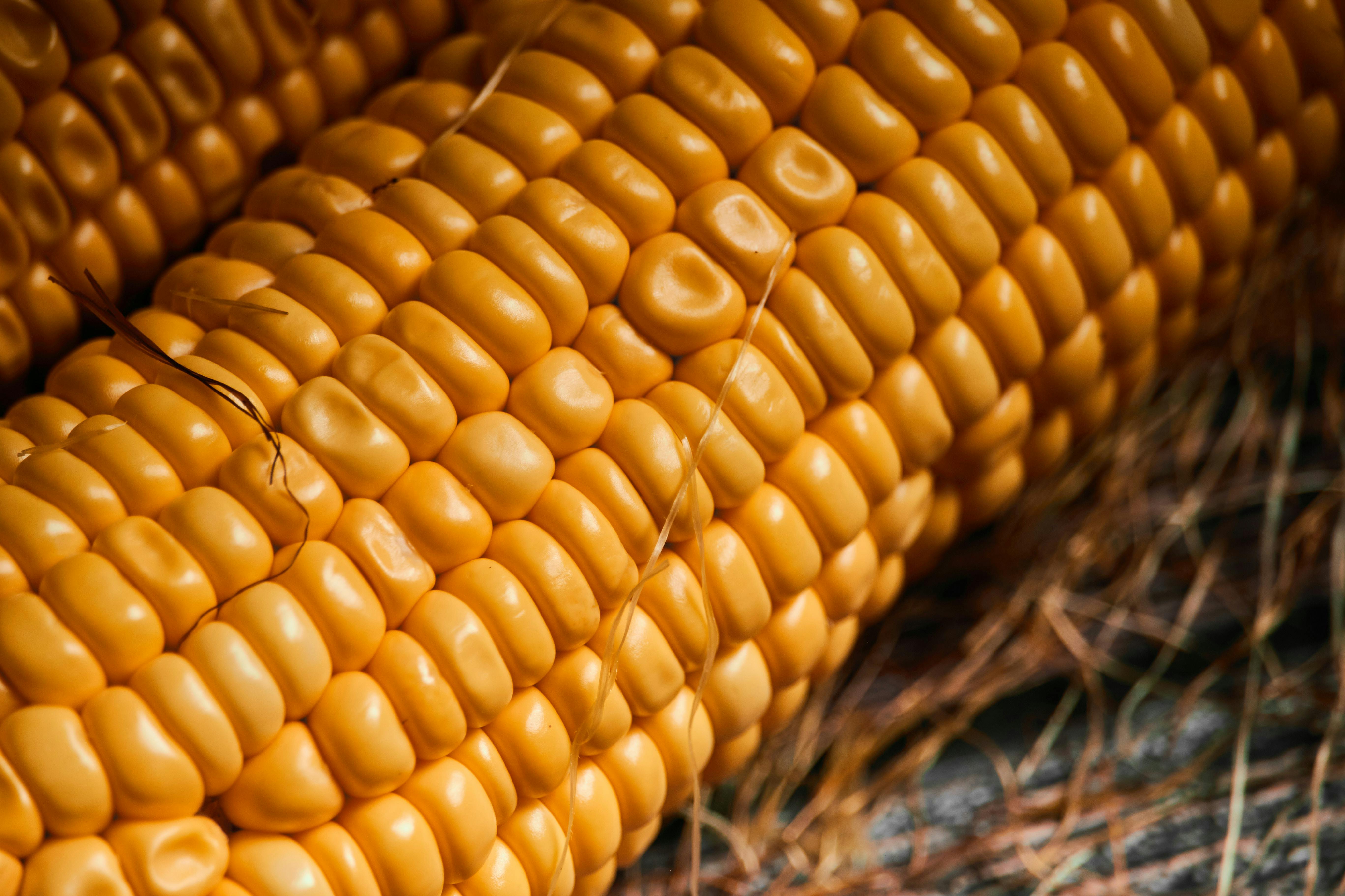
Don’t try to eat it — you’ll break your teeth. Yellow dent corn is harvested when full of starch and hard as a rock. Credit: Marjhan Ramboyong.
The corn used for ethanol production is not the same as the corn-on-the-cob at a summer barbecue or that comes in plastic bags of frozen Niblets. Those products use sweet corn bred specifically to pack extra simple sugars and less starch into their kernels, which is harvested while the corn plant is still alive and the kernels are still tender. Field corn, on the other hand, is bred to produce as much starch as possible, and is left in the field until the stalks are dead and the kernels have converted almost all of their sugar into starch. This leaves the kernels dry and hard as a rock, and often with a dimple in their top face that gives them their other name, dent corn.
Each kernel of corn is a fruit, at least botanically, with all the genetic information needed to create a new corn plant. That’s carried in the germ of the kernel, a relatively small part of the kernel that contains the embryo, a bit of oil, and some enzymes. The bulk of the kernel is taken up by the endosperm, the energy reserve used by the embryo to germinate, and as a food source until photosynthesis kicks in. That energy reserve is mainly composed of starch, which will power the fermentation process to come.
Starch is mainly composed of two different but related polysaccharides, amylose and amylopectin. Both are polymers of the simple six-carbon sugar glucose, but with slightly different arrangements. Amylose is composed of long, straight chains of glucose molecules bound together in what’s called an α-1,4 glycosidic bond, which just means that the hydroxyl group on the first carbon of the first glucose is bound to the hydroxyl on the fourth carbon of the second glucose through an oxygen atom:
Amylose, one of the main polysaccharides in starch. The glucose subunits are connected in long, unbranched chains up to 500 or so residues long. The oxygen atom binding each glucose together comes from a reaction between the OH radicals on the 1 and 4 carbons, with one oxygen and two hydrogens leaving in the form of water.
Amylose chains can be up to about 500 or so glucose subunits long. Amylopectin, on the other hand, has shorter straight chains but also branches formed between the number one and number six carbon, an α-1,6 glycosidic bond. The branches appear about every 25 residues or so, making amylopectin much more tangled and complex than amylose. Amylopectin makes up about 75% of the starch in a kernel.
Slurry Time
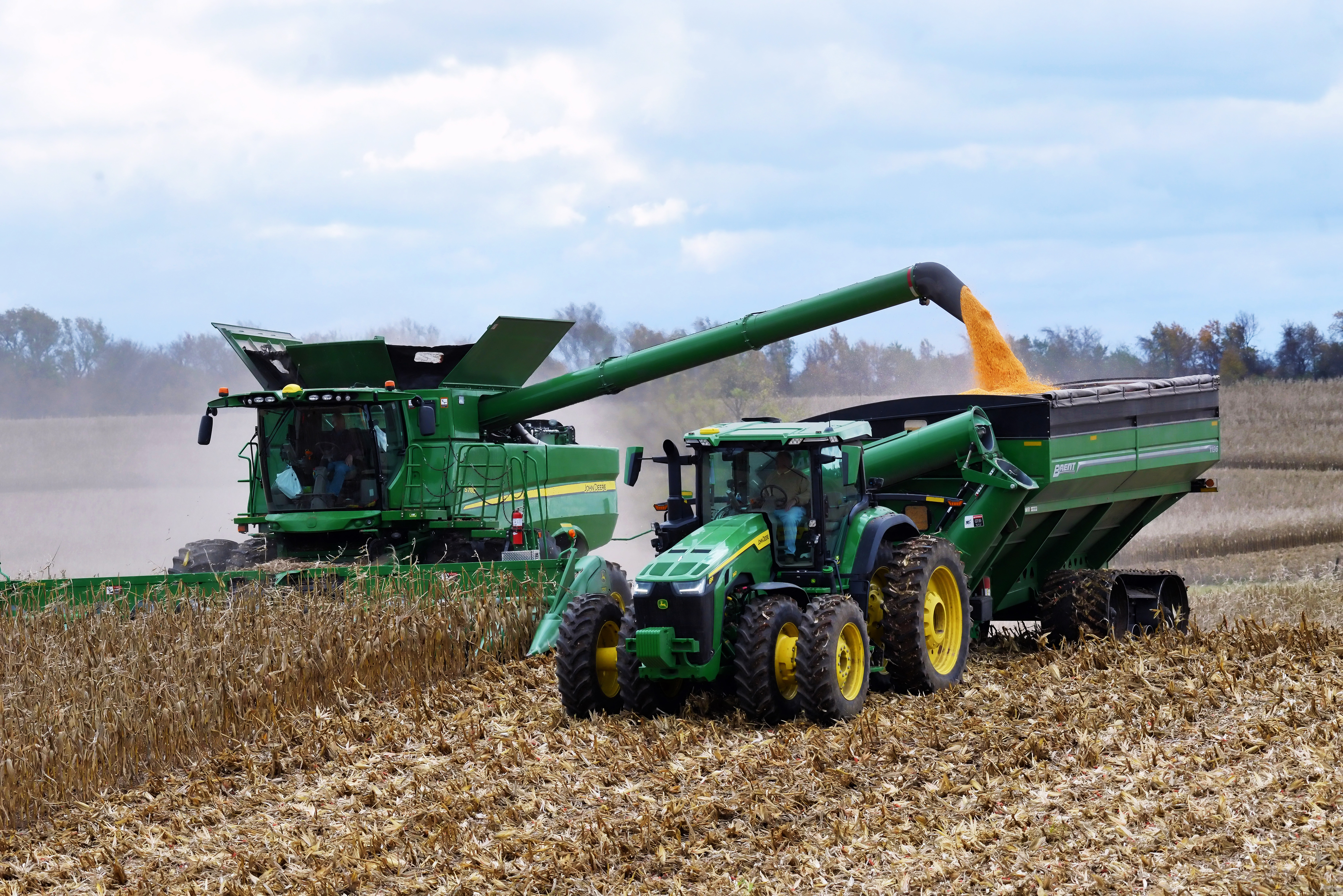
Ethanol production begins with harvesting corn using combine harvesters. These massive machines cut down dozens of rows of corn at a time, separating the ears from the stalks and feeding them into a threshing drum, where the kernels are freed from the cob. Winnowing fans and sieves separate the chaff and debris from the kernels, which are stored in a tank onboard the combine until they can be transferred to a grain truck for transport to a grain bin for storage and further drying.
Corn harvest in progress. You’ve got to burn a lot of diesel to make ethanol. Credit: dvande – stock.adobe.com
Once the corn is properly dried, open-top hopper trucks or train cars transport it to the distillery. The first stop is the scale house, where the cargo is weighed and a small sample of grain is taken from deep within the hopper by a remote-controlled vacuum arm. The sample is transported directly to the scale house for a quick quality assessment, mainly based on moisture content but also the physical state of the kernels. Loads that are too wet, too dirty, or have too many fractured kernels are rejected.
Loads that pass QC are dumped through gates at the bottom of the hoppers into a pit that connects to storage silos via a series of augers and conveyors. Most ethanol plants keep a substantial stock of corn, enough to run the plant for several days in case of any supply disruption. Ethanol plants operate mainly in batch mode, with each batch taking several days to complete, so a large stock ensures the efficiency of continuous operation.
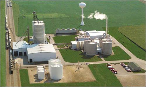
The Lakota Green Plains ethanol plant in Iowa. Ethanol plants look a lot like small petroleum refineries and share some of the same equipment. Source: MsEuphonic, CC BY-SA 3.0.
To start a batch of ethanol, corn kernels need to be milled into a fine flour. Corn is fed to a hammer mill, where large steel weights swinging on a flywheel smash the tough pericarp that protects the endosperm and the germ. The starch granules are also smashed to bits, exposing as much surface area as possible. The milled corn is then mixed with clean water to form a slurry, which can be pumped around the plant easily.
The first stop for the slurry is large cooking vats, which use steam to gently heat the mixture and break the starch into smaller chains. The heat also gelatinizes the starch, in a process that’s similar to what happens when a sauce is thickened with a corn starch slurry in the kitchen. The gelatinized starch undergoes liquefaction under heat and mildly acidic conditions, maintained by injecting sulfuric acid or ammonia as needed. These conditions begin hydrolysis of some of the α-1,4 glycosidic bonds, breaking the amylose and amylopectin chains down into shorter fragments called dextrin. An enzyme, α-amylase, is also added at this point to catalyze the α-1,4 bonds to create free glucose monomers. The α-1,6 bonds are cleaved by another enzyme, α-amyloglucosidase.
The Yeast Get Busy
The result of all this chemical and enzymatic action is a glucose-rich mixture ready for fermentation. The slurry is pumped to large reactor vessels where a combination of yeasts is added. Saccharomyces cerevisiae, or brewer’s yeast, is the most common, but other organisms can be used too. The culture is supplemented with ammonia sulfate or urea to provide the nitrogen the growing yeast requires, along with antibiotics to prevent bacterial overgrowth of the culture.
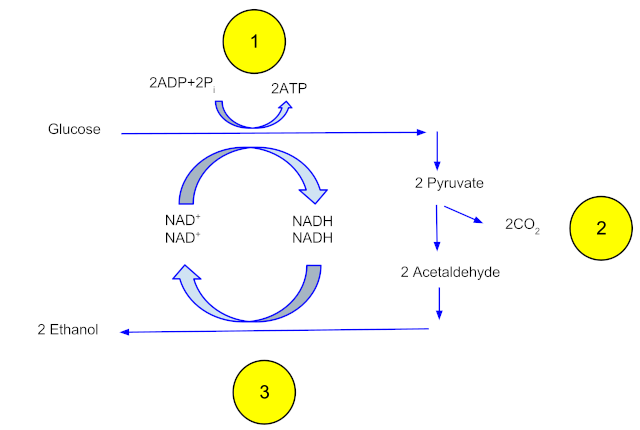
Fermentation occurs at around 30 degrees C over two to three days, while the yeast gorge themselves on the glucose-rich slurry. The glucose is transported into the yeast, where each glucose molecule is enzymatically split into two three-carbon pyruvate molecules. The pyruvates are then broken down into two molecules of acetaldehyde and two of CO2. The two acetaldehyde molecules then undergo a reduction reaction that creates two ethanol molecules. The yeast benefits from all this work by converting two molecules of ADP into two molecules of ATP, which captures the chemical energy in the glucose molecule into a form that can be used to power its metabolic processes, including making more yeast to take advantage of the bounty of glucose.
Anaerobic fermentation of one mole of glucose yields two moles of ethanol and two moles of CO2.
After the population of yeast grows to the point where they use up all the glucose, the mix in the reactors, which contains about 12-15% ethanol and is referred to as beer, is pumped into a series of three distillation towers. The beer is carefully heated to the boiling point of ethanol, 78 °C. The ethanol vapors rise through the tower to a condenser, where they change back into the liquid phase and trickle down into collecting trays lining the tower. The liquid distillate is piped to the next two towers, where the same process occurs and the distillate becomes increasingly purer. At the end of the final distillation, the mixture is about 95% pure ethanol, or 190 proof. That’s the limit of purity for fractional distillation, thanks to the tendency of water and ethanol to form an azeotrope, a mixture of two or more liquids that boils at a constant temperature. To drive off the rest of the water, the distillate is pumped into large tanks containing zeolite, a molecular sieve. The zeolite beads have pores large enough to admit water molecules, but too small to admit ethanol. The water partitions into the zeolite, leaving 99% to 100% pure (198 to 200 proof) ethanol behind. The ethanol is mixed with a denaturant, usually 5% gasoline, to make it undrinkable, and pumped into storage tanks to await shipping.
Nothing Goes to Waste
The muck at the bottom of the distillation towers, referred to as whole stillage, still has a lot of valuable material and does not go to waste. The liquid is first pumped into centrifuges to separate the remaining grain solids from the liquid. The solids, called wet distiller’s grain or WDG, go to a rotary dryer, where hot air drives off most of the remaining moisture. The final product is dried distiller’s grain with solubles, or DDGS, a high-protein product used to enrich animal feed. The liquid phase from the centrifuge is called thin stillage, which contains the valuable corn oil from the germ. That’s recovered and sold as an animal feed additive, too.
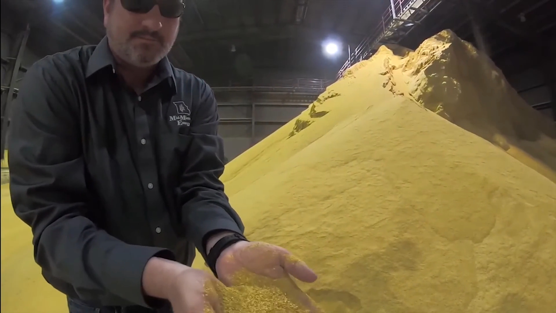
Ethanol fermentation produces mountains of DDGS, or dried distiller’s grain solubles. This valuable byproduct can account for 20% of an ethanol plant’s income. Source: Inside an Ethanol Plant (YouTube).
The final valuable product that’s recovered is the carbon dioxide. Fermentation produces a lot of CO2, about 17 pounds per bushel of feedstock. The gas is tapped off the tops of the fermentation vessels by CO2 scrubbers and run through a series of compressors and coolers, which turn it into liquid carbon dioxide. This is sold off by the tanker-full to chemical companies, food and beverage manufacturers, who use it to carbonate soft drinks, and municipal water treatment plants, where it’s used to balance the pH of wastewater.
There are currently 187 fuel ethanol plants in the United States, most of which are located in the Midwest’s corn belt, for obvious reasons. Together, these plants produced more than 16 billion gallons of ethanol in 2024. Since each bushel of corn yields about 3 gallons of ethanol, that translates to an astonishing 5 billion bushels of corn used for fuel production, or about a third of the total US corn production.
From Blog – Hackaday via this RSS feed
Our hacker [Andrew Zonenberg] reports in on his open-source high-speed Ethernet switch. He hasn’t finished yet, but progress has been made.
If you were wondering what might be involved in a high-speed Ethernet switch implementation look no further. He’s been working on this project, on and off, since 2012. His design now includes a dizzying array of parts. [Andrew] managed to snag some XCKU5P FPGAs for cheap, paying two cents in the dollar, and having access to this fairly high-powered hardware affected the project’s direction.
You might be familiar with [Andrew Zonenberg] as we have heard from him before. He’s the guy who gave us the glscopeclient, which is now ngscopeclient.
As perhaps you know, when he says in his report that he is an “experienced RTL engineer”, he is talking about Register-Transfer Level, which is an abstraction layer used by hardware description languages, such as Verilog and VHDL, which are used to program FPGAs. When he says “RTL” he’s not talking about Resistor-Transistor Logic (an ancient method of developing digital hardware) or the equally ancient line of Realtek Ethernet controllers such as the RTL8139.
When it comes to open-source software you can usually get a copy at no cost. With open-source hardware, on the other hand, you might find yourself needing to fork out for some very expensive bits of kit. High speed is still expensive! And… proprietary, for now. If you’re looking to implement Ethernet hardware today, you will have to stick with something slower. Otherwise, stay tuned, and watch this space.
From Blog – Hackaday via this RSS feed
Although plenty of us have our preferred language for coding, whether it’s C for its hardware access, Python for its usability, or Fortran for its mathematic prowess, not every language is specifically built for problem solving of a particular nature. Some are built as thought experiments or challenges, like Whitespace or Chicken but aren’t used for serious programming. There are a few languages that fit in the gray area between these regions, and one example of this is the language MOUSE which can now be run on an Arduino.
Although MOUSE was originally meant to be a minimalist language for computers of the late 70s and early 80s with limited memory (even for the era), its syntax looks more like a more modern esoteric language, and indeed it arguably would take a Python developer a bit of time to get used to it in a similar way. It’s stack-based, for a start, and also uses Reverse Polish notation for performing operations. The major difference though is that programs process single letters at a time, with each letter corresponding to a specific instruction. There have been some changes in the computing world since the 80s, though, so [Ivan]’s version of MOUSE includes a few changes that make it slightly different than the original language, but in the end he fits an interpreter, a line editor, graphics primitives, and peripheral drivers into just 2KB of SRAM and 32KB Flash so it can run on an ATmega328P.
There are some other features here as well, including support for PS/2 devices, video output, and the ability to save programs to the internal EEPROM. It’s an impressive setup for a language that doesn’t get much attention at all, but certainly one that threads the needle between usefulness and interesting in its own right. Of course if a language where “Hello world” is human-readable is not esoteric enough, there are others that may offer more of a challenge.
From Blog – Hackaday via this RSS feed
For all that “should have used a 555” is a bit of a meme around here, there’s some truth to it. The humble 555 is a wonderful tool in the right hands. That’s why it’s wonderful to see this all-analog stylus synth project by EE student [DarcyJ] bringing the 555 out for the new generation.
The project is heavily inspired by the vintage stylophone, but has some neat tweaks. A capacitor bank means multiple octaves are available, and using a ladder of trim pots instead of fixed resistors makes every note tunable. [Darcy] of course included the vibrato function of the original, and yes, he used a 555 for that, too. He put a trim pot on that, too, to control the depth of vibrato, which we don’t recall seeing on the original stylophone.
The writeup is very high quality and could be recommended to anyone just getting started in analog (or analogue) electronics– not only does [Darcy] explain his design process, he also shows his pratfalls and mistakes, like in the various revisions he went through before discovering the push-pull amplifier that ultimately powers the speaker.
Since each circuit is separately laid out and indicated on the PCB [Darcy] designed in KiCad for this project. Between that and everything being thru-hole, it seems like [Darcy] has the makings of a lovely training kit. If you’re interested in rolling your own, the files are on GitHub under a CERN-OHL-S v2 license,and don’t forget to check out the demo video embedded below to hear it in action.
Of course, making music on the 555 is hardly a new hack. We’ve seen everything from accordions to paper-tape player pianos to squonkboxes over the years. Got another use for the 555? Let us know about it, in the inevitable shill for our tip line you all knew was coming.
From Blog – Hackaday via this RSS feed
Although the idea of containing a plasma within a magnetic field seems straightforward at first, plasmas are highly dynamic systems that will happily escape magnetic confinement if given half a chance. This poses a major problem in nuclear fusion reactors and similar, where escaping particles like alpha (helium) particles from the magnetic containment will erode the reactor wall, among other issues. For stellarators in particular the plasma dynamics are calculated as precisely as possible so that the magnetic field works with rather than against the plasma motion, with so far pretty good results.
Now researchers at the University of Texas reckon that they can improve on these plasma system calculations with a new, more precise and efficient method. Their suggested non-perturbative guiding center model is published in (paywalled) Physical Review Letters, with a preprint available on Arxiv.
The current perturbative guiding center model admittedly works well enough that even the article authors admit to e.g. Wendelstein 7-X being within a few % of being perfectly optimized. While we wouldn’t dare to take a poke at what exactly this ‘data-driven symmetry theory’ approach exactly does differently, it suggests the use machine-learning based on simulation data, which then presumably does a better job at describing the movement of alpha particles through the magnetic field than traditional simulations.
Top image: Interior of the Wendelstein 7-X stellarator during maintenance.
From Blog – Hackaday via this RSS feed
There’s a section of our community who concern themselves with the technological aspects of preparing for an uncertain future, and for them a significant proportion of effort goes in to communication. This has always included amateur radio, but in more recent years it has been extended to LoRa. To that end, [Bertrand Selva] has created a LoRa communicator, one which uses a Pi Pico, and delivers secure messaging.
The hardware is a rather-nice looking 3D printed case with a color screen and a USB A port for a keyboard, but perhaps the way it works is more interesting. It takes a one-time pad approach to encryption, using a key the same length as the message. This means that an intercepted message is in effect undecryptable without the key, but we are curious about the keys themselves.
They’re a generated list of keys stored on an SD card with a copy present in each terminal on a particular net of devices, and each key is time-specific to a GPS derived time. Old keys are destroyed, but we’re interested in how the keys are generated as well as how such a system could be made to survive the loss of one of those SD cards. We’re guessing that just as when a Cold War spy had his one-time pad captured, that would mean game over for the security.
So if Meshtastic isn’t quite the thing for you then it’s possible that this could be an alternative. As an aside we’re interested to note that it’s using a 433 MHz LoRa module, revealing the different frequency preferences that exist between enthusiasts in different countries.
From Blog – Hackaday via this RSS feed
In the early days of the World Wide Web – with the Year 2000 and the threat of a global collapse of society were still years away – the crafting of a website on the WWW was both special and increasingly more common. Courtesy of free hosting services popping up left and right in a landscape still mercifully devoid of today’s ‘social media’, the WWW’s democratizing influence allowed anyone to try their hands at web design. With varying results, as those of us who ventured into the Geocities wilds can attest to.
Back then we naturally had web standards, courtesy of the W3C, though Microsoft, Netscape, etc. tried to upstage each other with varying implementation levels (e.g. no iframes in Netscape 4.7) and various proprietary HTML and CSS tags. Most people were on dial-up or equivalently anemic internet connections, so designing a website could be a painful lesson in optimization and targeting the lowest common denominator.
This was also the era of graceful degradation, where us web designers had it hammered into our skulls that using and navigating a website should be possible even in a text-only browser like Lynx, w3m or antique browsers like IE 3.x. Fast-forward a few decades and today the inverse is true, where it is your responsibility as a website visitor to have the latest browser and fastest internet connection, or you may even be denied access.
What exactly happened to flip everything upside-down, and is this truly the WWW that we want?
User Vs Shinies
Back in the late 90s, early 2000s, a miserable WWW experience for the average user involved graphics-heavy websites that took literal minutes to load on a 56k dial-up connection. Add to this the occasional website owner who figured that using Flash or Java applets for part of, or an entire website was a brilliant idea, and had you sit through ten minutes (or more) of a loading sequence before being able to view anything.
Another contentious issue was that of the back- and forward buttons in the browser as the standard way to navigate. Using Flash or Java broke this, as did HTML framesets (and iframes), which not only made navigating websites a pain, but also made sharing links to a specific resource on a website impossible without serious hacks like offering special deep links and reloading that page within the frameset.
As much as web designers and developers felt the lure of New Shiny Tech to make a website pop, ultimately accessibility had to be key. Accessibility, through graceful degradation, meant that you could design a very shiny website using the latest CSS layout tricks (ditching table-based layouts for better or worse), but if a stylesheet or some Java- or VBScript stuff didn’t load, the user would still be able to read and navigate, at most in a HTML 1.x-like fashion. When you consider that HTML is literally just a document markup language, this makes a lot of sense.
Credit: Babbage, Wikimedia.
More succinctly put, you distinguish between the core functionality (text, images, navigation) and the cosmetics. When you think of a website from the perspective of a text-only browser or assistive technology like screen readers, the difference should be quite obvious. The HTML tags mark up the content of the document, letting the document viewer know whether something is a heading, a paragraph, and where an image or other content should be referenced (or embedded).
If the viewer does not support stylesheets, or only an older version (e.g. CSS 2.1 and not 3.x), this should not affect being able to read text, view images and do things like listen to embedded audio clips on the page. Of course, this basic concept is what is effectively broken now.
It’s An App Now
Somewhere along the way, the idea of a website being an (interactive) document seems to have been dropped in favor of a the website instead being a ‘web application’, or web app for short. This is reflected in the countless JavaScript, ColdFusion, PHP, Ruby, Java and other frameworks for server and client side functionality. Rather than a document, a ‘web page’ is now the UI of the application, not unlike a graphical terminal. Even the WordPress editor in which this article was written is in effect just a web app that is in constant communication with the remote WordPress server.
This in itself is not a problem, as being able to do partial page refreshes rather than full on page reloads can save a lot of bandwidth and copious amounts of sanity with preserving page position and lack of flickering. What is however a problem is how there’s no real graceful degradation amidst all of this any more, mostly due to hard requirements for often bleeding edge features by these frameworks, especially in terms of JavaScript and CSS.
Sometimes these requirements are apparently merely a way to not do any testing on older or alternative browsers, with ‘forum’ software Discourse (not to be confused with Disqus) being a shining example here. It insists that you must have the ‘latest, stable release’ of either Microsoft Edge, Google Chrome, Mozilla Firefox or Apple Safari. Purportedly this is so that the client-side JavaScript (Ember.js) framework is happy, but as e.g. Pale Moon users have found out, the problem is with a piece of JS that merely detects the browser, not the features. Blocking the browser-detect-* script in e.g. an adblocker restores full functionality to Discourse-afflicted pages.
Wrong Focus
It’s quite the understatement to say that over the past decades, websites have changed. For us greybeards who were around to admire the nascent WWW, things seemed to move at a more gradual pace back then. Multimedia wasn’t everywhere yet, and there was no Google et al. pushing its own agenda along with Digital Restrictions Management (DRM) onto us internet users via the W3C, which resulted in the EFF resigning in protest.
Google Search open in the Pale Moon browser.
Although Google et al. ostensibly profess to have only our best interests at heart when features were added to Chrome, the very capable plugins system from Netscape and Internet Explorer taken out back and WebExtensions Manifest V3 introduced (with the EFF absolutely venomous about the latter), privacy concerns are mounting amidst concerns that corporations now control the WWW, with even new HTML, CSS and JS features being pushed by Google solely for its use in Chrome.
For those of us who still use traditional browsers like Pale Moon (forked from Firefox in 2009), it is especially the dizzying pace of new ‘features’ that discourages us from using effectively non-Chromium-based browsers, with websites all too often having only been tested in Chrome. Functionality in Safari, Pale Moon, etc. often is more a matter of luck as the assumption is made by today’s crop of web devs that everyone uses the latest and greatest Chrome browser version. This ensures that using non-Chromium browsers is fraught with functionally defective websites, as the ‘Web Compatibility Support’ section of the Pale Moon forum illustrates.
Question is whether this is the web which we, the users, want to see.
Low-Fidelity Feature
Another unpleasant side-effect of web apps is that they force an increasing amount of JS code to be downloaded, compiled and ran. This contrasts with plain HTML and CSS pages that tend to be mere kilobytes in size in addition to any images. Back in The Olden Days browsers gave you the option to disable JavaScript, as the assumption was that JS wasn’t used for anything critical. These days if you try to browse with e.g. a JS blocking extension like NoScript, you’ll rapidly find that there’s zero consideration for this, and many sites will display just a white page because they rely on a JS-based stub to do the actual rendering of the page rather than the browser.
In this and earlier described scenarios the consequence is the same: you must be using the latest Chromium-based browser to use many sites, you will be using a lot of RAM and CPU for even basic pages, and forget about using retro- or alternative systems that do not support the latest encryption standards and certificates.
The latter is due to the removal of non-encrypted HTTP from many browsers, because for some reason downloading public information from HTTP and FTP sites without encrypting said public data is a massive security threat now, and the former is due to the frankly absurd amounts of JS, with the Task Manager feature in many browsers showing the resource usage per tab, e.g.:
The Task Manager in Microsoft Edge showing a few active tabs and their resource usage.
Of these tabs, there is no way to reduce their resource usage, no ‘graceful degradation’ or low-fidelity mode, so that older systems as well as the average smart phone or tablet will struggle or simply keel over to keep up with the demands of the modern WWW, with even a basic page using more RAM than the average PC had installed by the late 90s.
Meanwhile the problems that we web devs were moaning about around 2000 such as an easy way to center content with CSS got ignored, while some enterprising developers have done the hard work of solving the graceful degradation problem themselves. A good example of this is the FrogFind! search engine, which strips down DuckDuckGo search results even further, before passing any URLs you click through a PHP port of Mozilla’s Readability. This strips out anything but the main content, allowing modern website content to be viewed on systems with browsers that were current in the very early 1990s.
In short, graceful degradation is mostly an issue of wanting to, rather than it being some kind of unsurmountable obstacle. It requires learning the same lessons as the folk back in the Flash and Java applet days had to: namely that your visitors don’t care how shiny your website, or how much you love the convoluted architecture and technologies behind it. At the end of the day your visitors Just Want Things to Work, even if that means missing out on the latest variation of a Flash-based spinning widget or something similarly useless that isn’t content.
Tl;dr: content is for your visitors, the eyecandy is for you and your shareholders.
From Blog – Hackaday via this RSS feed
What can you do if your circuit repair diagnosis indicates an open circuit within an integrated circuit (IC)? Your IC got too hot and internal wiring has come loose. You could replace the IC, sure. But what if the IC contains encryption secrets? Then you would be forced to grind back the epoxy and fix those open circuits yourself. That is, if you’re skilled enough!
In this video our hacker [YCS] fixes a Mercedes-Benz encryption chip from an electronic car key. First, the black epoxy surface is polished off, all the way back to the PCB with a very fine gradient. As the gold threads begin to be visible we need to slow down and be very careful.
The repair job is to reconnect the PCB points with the silicon body inside the chip. The PCB joints aren’t as delicate and precious as the silicon body points, those are the riskiest part. If you make a mistake with those then repair will be impossible. Then you tin the pads using solder for the PCB points and pure tin and hot air for the silicon body points.
Once that’s done you can use fine silver wire to join the points. If testing indicates success then you can complete the job with glue to hold the new wiring in place. Everything is easy when you know how!
Does repair work get more dangerous and fiddly than this? Well, sometimes.
Thanks to [J. Peterson] for this tip.
From Blog – Hackaday via this RSS feed
Normal people binge-scroll social media. Hackaday writers tend to pore through online tech news and shopping sites incessantly. The problem with the shopping sites is that you wind up buying things, and then you have even more projects you don’t have time to do. That’s how I found the MAKE-roscope, an accessory aimed at kids that turns a cell phone into a microscope. While it was clearly trying to appeal to kids, I’ve had some kids’ microscopes that were actually useful, and for $20, I decided to see what it was about. If nothing else, the name made it appealing.
My goal was to see if it would be worth having for the kinds of things we do. Turns out, I should have read more closely. It isn’t really going to help you with your next PCB or to read that tiny print on an SMD part. But it is interesting, and — depending on your interests — you might enjoy having one. The material claims the scope can magnify from 125x to 400x.
What Is It?
A microscope in a tin. Just add a cell phone or tablet
The whole thing is in an unassuming Altoids-like tin. Inside the box are mostly accessories you may or may not need, like a lens cloth, a keychain, plastic pipettes, and the like. There are only three really interesting things: A strip of silicone with a glass ball in it, and a slide container with five glass slides, three of which have something already on them. There’s also a spare glass ball (the lens).
What I didn’t find in my box were cover slips, any way to prepare specimens, and — perhaps most importantly — clear instructions. There are some tiny instructions on the back of the tin and on the lens cloth paper. There is also a QR code, but to really get going, I had to watch a video (embedded below).
What I quickly realized is that this isn’t a metalurgical scope that takes images of things. It is a transmissive microscope like you find in a biology lab. Normally, the light in a scope like that goes up through the slide and into the objective. This one is upside down. The light comes from the top, through the slide, and into the glass ball lens.
Bio Scopes Can Be Fun
Of course, if you have an interest in biology or thin films or other things that need that kind of microscope, this could be interesting. After all, cell phones sometimes have macro modes that you can use as a pretty good low-power microscope already if you want to image a part or a PCB. You can also find lots of lenses that attach to the phone if you need them. But this is a traditional microscope, which is a bit different.
The silicone compresses, which seems to be the real trick. Here’s how it works in practice. You turn on your camera and switch to the selfie lens. Then you put the silicone strip over the camera and move it around. You’ll see that the lens makes a “spotlight” in the image when it is in the right place. Get it centered and zoom until you can’t see the circle of the lens anymore.
Then you put your slide down on the lens and move it around until you get an image. It might be a little fuzzy. That’s where the silicone comes in. You push down, and the image will snap into focus. The hardest part is pushing down while holding it still and pushing the shutter button.
Zeiss and Nikon don’t have anything to worry about, but the images are just fine. You can grab a drop of water or swab your cheek. It would have been nice to have some stain and either some way to microtome samples, or at least instructions on how you might do that with household items.
Verdict
For most electronics tasks, you are better off with a loupe, magnifiers, a zoomed cell phone, or a USB microscope. But if you want a traditional microscope for science experiments or to foster a kid’s interest in science, it might be worth something.
For electronics, you are better off with a metallurgical scope. Soldering under a stereoscope is life-changing. We’ve seen more expensive versions of this, too, but we aren’t sure they are much better.
From Blog – Hackaday via this RSS feed