1
Electrical and Computer Engineering
2960 readers
13 users here now
Electrical and computer engineering (ECE) community, for professionals and learners. Discuss ECE related topics here, for instance digital design, signal processing, circuit analysis, electromagnetics, microelectronics, power electronics, RF electronics, etc.
founded 2 years ago
MODERATORS
2
3
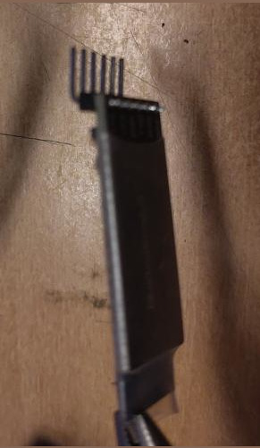
I ordered a MiniTools test clip to start experimenting with flashing EEPROMs. There was no information on the retailer's website regarding the width of the pins. This is what I got:

I asked MiniTools if they have any solution to this. They said "no". I then realized that this clip was probably meant for soldering. Which I haven't had the energy to learn yet.
I ended up buying the expensive Pomodo one.
The flashing went well.
4
cross-posted from: https://programming.dev/post/47186720
Edit: this guide doesn't seem to mention it https://pcsupport.lenovo.com/us/en/products/laptops-and-netbooks/thinkpad-t-series-laptops/thinkpad-t480-type-20l5-20l6/20l6/20l6s01q2y/document-userguide
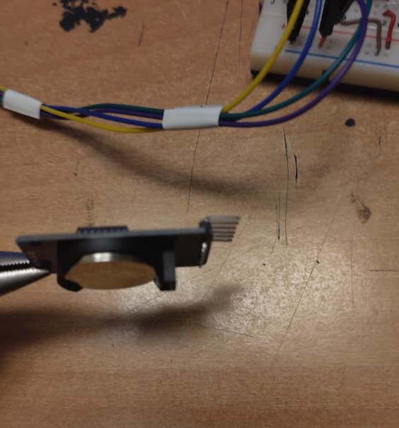
I was flashing Libreboot on to my ThinkPad T480, when I noticed this little button. Sorry for the poor images!


5
6
7
8
9
-4
Intricuit Magic Screen Turns Any MacBook Into a Touchscreen: The Most Surprising CES 2026 Gadget
(techfusiondaily.com)
10
11
12
1
China figured out how to sell EVs. Now it has to deal with their aging batteries.
(www.technologyreview.com)
13
14
15
16
17
7
Question about KiCAD footprints for breakout boards with right angle male headers sticking outside the "box" of the board
(programming.dev)
Hello guys.
I'm trying to learn some more KiCAD and general electronics design from scratch by continuing my thesis project after I've submitted it and its all done, but by taking it to the next step and actually getting a PCB and soldering everything on. This is to get experience through the entire process from design to assembly.
Where I'm stuck is at creating the footprints for my components. I've watched a bunch of videos about the topic, but they all seem to be for boards with no header pins attached to them, or for pins that are vertical (perpendicular to the actual board). The two boards I have are breakout boards for a DS3231 RTC and an HM-10 BLE module, and they both have right-angle male header pins sticking out, which obviously made prototyping on a breadboard really easy, but I'm struggling with converting them to PCB.
Here are some photos to make it clearer:
HM-10:
DS3231:
I know one of my options is to desolder the right-angle header pins and add straight pins to them, but I'd like to avoid that so that I can easily use them in any future projects by simply disconnecting them from the eventual PCB and using them in a breadboard.
As such, I know that I would like there to be female headers on the final PCB, and ideally the female headers will also be at a right-angle so that the final PCB is a little more compact and there aren't just some boards sticking out from it.
So, after getting some measurements with my calipers, how can I translate them into the KiCAD footprint editor knowing the footprint should include the female right-angle header pins (which will of course extend the length of the modules beyond what I have currently measured), and also take their height into account so that they don't have any obstacles between them and the PCB as they are laying parallel to it?
I hope I made myself clear enough, but if not please feel free to ask me for any clarification.
Thanks in advance for any replies :)
18
19
20
21
22
23
19
Why recycling solar panels is harder than you might think − an electrical engineer explains
(theconversation.com)
24
25
view more: next ›