1
Electronics
2653 readers
2 users here now
Projects, pictures, industry discussions and news about electronic engineering & component-level electronic circuits.
Rules
1: Be nice.
2: Be on-topic (eg: Electronic, not electrical).
3: No commercial stuff, buying, selling or valuations.
4: No circuit design or repair, tools or component questions.
5: No excessively promoting your own sites, social media, videos etc.
Ask questions in https://discuss.tchncs.de/c/askelectronics
founded 2 years ago
MODERATORS
2
3
4
5
6
7
8
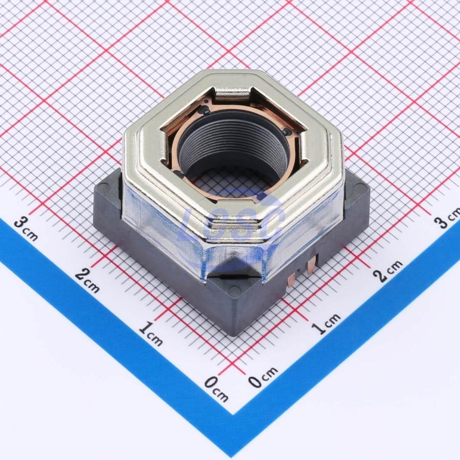
Source: https://lcsc.com/product-detail/Vibration-Motors_Lian-Xin-Technology-XDMD-YB200-08_C47118014.html
Applying current changes the vertical position. You would glue a lens onto this and place it above your camera sensor.
Machine-translated page from the datasheet:

9
10
11
12
13
14
The SCD4x sensor from Sensirion measures CO₂, temperature, and humidity, and communicates these values via I²C.

The measurement principle for the CO2 is that of photoacoustic sensing. The fundamental principle is shown in the diagram below: shine light that the CO2 molecules absorb and use a microphone to listen to the pressure variations.

I ordered a batch of SCD41 sensors from China for various projects, including fermentation, mushroom and plant cultivation, and field monitoring.
Since I had extras, I sacrificed one for macro photography. I removed the cover with a dremel and pliers, then cleaned the internals using isopropanol.

Here is my take:
The temperature and humidity are measured by Sensirion’s SHT40, seen as the black square at the bottom right. It’s likely accessed by the internal microcontroller over an internal I²C bus.
The pink square at the top left is a MEMS IR emitter. The SCD4x datasheet doesn’t specify the emission wavelength, but 4.3 µm is standard for NDIR-based CO₂ detection. A similar emitter example is this one from Microhybrid. These emitters usually produce broadband IR, with a 4.3 µm band-pass interference filter on top. The pink hue likely comes from this filter. Filters like these are critical to target CO₂ absorption while avoiding spectral overlap with other gases. For further reading, see Infratec's application note and Delta Optical Thin Film’s technical explanation.
The gold component labeled “o119 ANC” is the MEMS microphone, used to detect pressure waves caused by gas molecules absorbing pulsed IR light—this is photoacoustic sensing. The vibration excited by 4.3 µm light occurs at ~70 THz, far beyond acoustic detection. However, the IR source is pulsed at a modulation frequency (typically 20–60 Hz, e.g. 40 Hz), and the microphone detects the resulting pressure variations at this frequency. The principle is outlined in patent US 2024/0133801 A1.
An example of a compatible MEMS microphone is Infineon’s IM72D128V01, which supports frequencies down to 20 Hz.
The final main component is the metal-shielded package. It likely contains a microcontroller responsible for:
- Driving the MEMS IR emitter with a modulated current (e.g., at 40 Hz)
- Capturing and analyzing the MEMS microphone signal to extract the amplitude of acoustic pressure oscillations (proportional to CO₂ concentration)
- Acting as an I²C master to retrieve temperature and humidity data from the SHT40
- Acting as an I²C slave to provide CO₂, temperature, and humidity data to an external controller
Here are top and bottom views of the sensor cap:


The cap has a circular gas inlet. The white material covering it is likely a hydrophobic ePTFE membrane, which allows gas exchange while blocking liquid water.
I hope someone else finds this interesting too!
EDIT: After posted this, I searched online and I found a photo from someone who went a deeper than me and did expose the microcontroller: https://www.hackteria.org/wiki/CO2_Soil_Respiration_Chamber
This is the photo borrowed from that site:

15
16
17
18
17
Offline inventory system that pulls info from barcodes' datasheets and creates labels, etc
(hackaday.com)
cross-posted from: https://rss.ponder.cat/post/159054
Binner Makes Workshop Parts Organization Easy
We’ve all had times where we knew we had some part but we had to go searching for it all over as it wasn’t where we thought we put it. Organizing the numerous components, parts, and supplies that go into your projects can be a daunting task, especially if you use the same type of part at different times for different projects. It helps to have a framework to keep track of all the small details. Binner is an open source project that aims to allow you to easily maintain a database that can be customized to your use.
In a recent video for DigiKey, [Byte Sized Engineer] used Binner to track the locations of his components and parts in his freshly organized workshop. Binner already has the ability to read the labels used by well-known electronics suppliers via a barcode scanner, and uses that information to populate your inventory. It even grabs quantities and links in a datasheet for your newly added part. The barcode scanner can also be used to retrieve the contents of a location, so with a single scan Binner can bring up everything residing at that location.
Binner can be run locally so there isn’t the concern of putting in all the effort to build up your database just to have an internet outage make it inaccessible. Another cool feature is that it allows you to print labels, you can customize the fields to display the values you care about.
The project already has future plans to tie into a “smart bin” system to light up the location of your component — a clever feature we’ve seen implemented in previous setups.


From Blog – Hackaday via this RSS feed
19
20
21
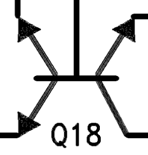
You can do all sorts of nifty things when you're designing silicon. Including this abomination.
https://en.wikipedia.org/wiki/Carcinisation
Source: datasheet for LM161, a high speed (20ns delay) moderately high voltage (30V) comparator. I'm going to try and make a discrete version of some bits of it and see how well it works. Maybe not this triple-emitter NPN though, I draw the line at components that require livestock sacrifices.

22
23
20
Two different sizes shown. Each has two inductors (grey bits) stuck to a capacitor (middle) with some metal end caps acting as terminals. There is a third terminal underneath the capacitor. Grid in background is 1mm, pics stolen from LCSC.
I think this taped picture is also really cool (stolen from here):

Datasheet: https://www.murata.com/en-global/products/productdata/8796766699550/ENFE0002.pdf
24
25
der8auer got the original 5090 card from the reddit melting cable post, then demonstrated that two of the six 12V power connector cables are having 20ish amps running through them and overheating, while the other 4 cables are not.

view more: next ›