Und alle 39 der insgesamt 11 NichtsBS Nutzer sind hier
Starfighter
joined 2 years ago
Indeed
Its a fully electric drivetrain with a gas generator. When the battery runs low you can recharge it (even while driving) using the generator.
So you don't have the complexity of a combined hybrid drivetrain, but instead a normal BEV one plus a power generator, both of which are very well understood problems.
Another benefit is that the generator can always run at its most efficient rpm/power point and is decoupled from the speed of the wheels.
Interestingly Wankel engines have been making a bit of a comeback for this purpose since they can be built more compactly for the same output power.
A drawback compared to hybrid drivetrains is that both components need to be built for "full" load, whilst a hybrid drivetrain can combine powers to reach maximum performance, meaning each of the motors only has to carry half (or part) of the total load.
SYN??
Rock and stone!
(Without the text I'd assume this was a Deep Rock Galactic artwork)
Just out of curiosity I don't see how 4 sticks die together at the exact same time unless the PSU is/has fucked up hard.
I'd argue that the likelihood of 4 sticks failing together is much lower than the MOBO or CPU or PSU failing in a way that makes RAM inaccessible.
Typically you'd see one stick failing at which point you could take it out and run with the other 3 (or 2 depending on configuration).
Anyway if you ever intend to return its probably best to keep the rest of the components because who knows which of those will be up next for a shortage/crisis.
I assume you mean AVIF? Because AV1 is not an image (file) format but a video compression format (that needs to be wrapped in container file formats to be storable).
SpinLaunch versucht ja etwas ganz ähnliches. Mit ~100km Atmosphäre über der Startrampe ist das Unterfangen nicht einfach.
SpinLaunch hat wenigstens den Vorteil, dass es auf dem Mond wesentlich besser funktionieren dürfte.
Stapler sein wie:

Well the front didn't fall off, so this could be typical for the new boosters.
The std::offload project is kinda cool. Hadn't heard about that before.
It'll be interesting to see where that leads.
Hi, this post is structured similarly to r/PrintedCircuitBoard 's review request format. Since we don't have any PCB communities over here yet, I thought that this might fit in here and can maybe spark some friendly discussion.
This is a relay board controlling electrically driven windows and blinds. For this purpose it has some additional connectors to a weather station, interior sensors and an LCD screen.
It is replacing a ~20 year old board that has started to develop some annoying quirks. I've mostly copied what the original board did and adjusted it for the ESP32. This is not a production board and if all goes well, I will only ever assemble a single one of these.
The primary usage scenario is that the MCU will monitor the weather station and then actuate the motor groups (M1 - M6 connected on J3 - J8) to keep the indoors temperature and humidity in check.
At least during summer time the board will likely run 24/7 and will hopefully be used for a number of years. For maintenance reasons I've tried to keep it simple and the component count low.
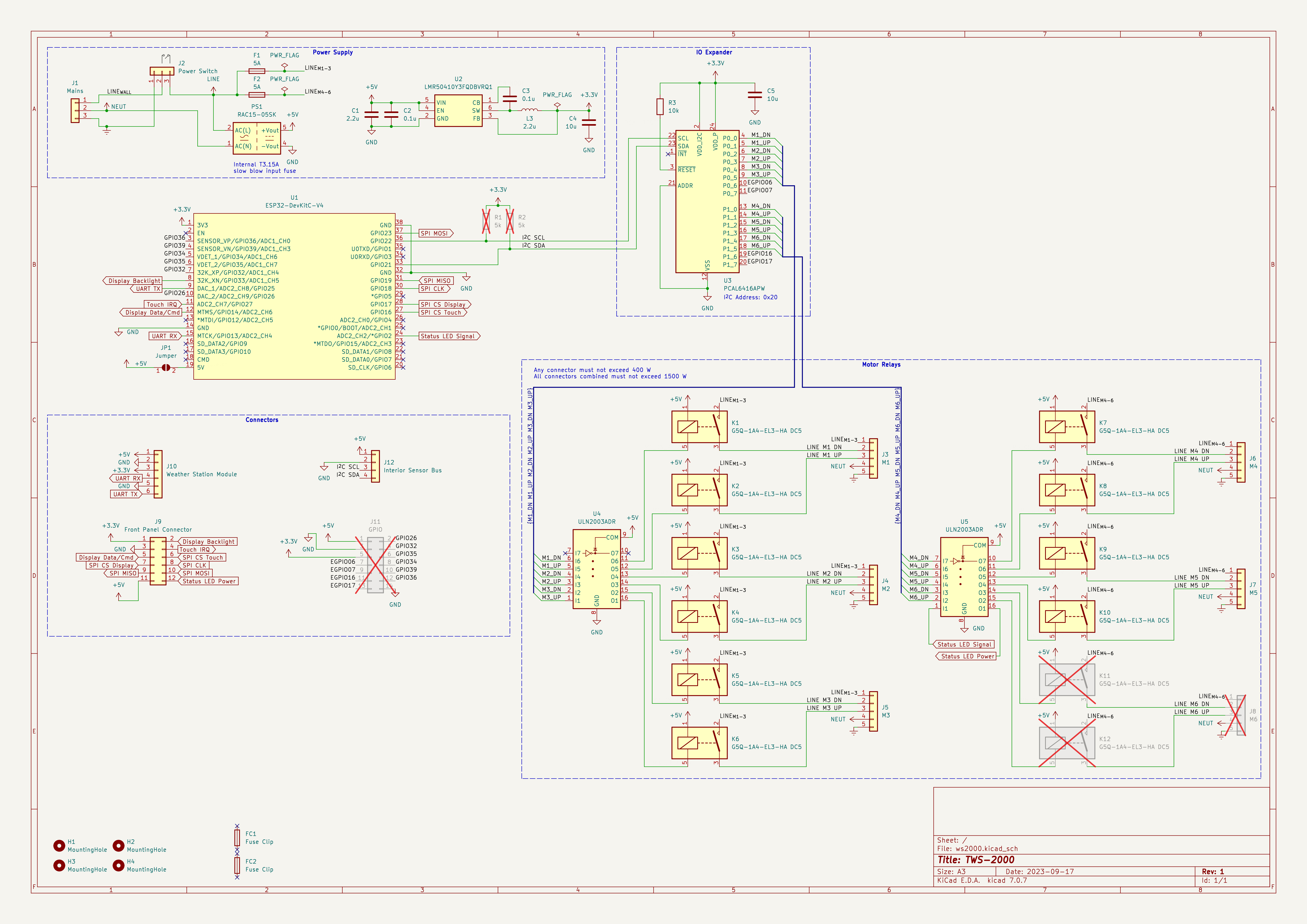
Mains power is supplied from J1 and being fed to the motors via the relays. PS1 converts the line voltage to +5V DC for the relay coils and some auxiliary components. The switching regulator U2 steps that down to +3.3V for the MCU U1 and IO Expander U3.
The board size is mostly constrained by the preexisting mounting holes which gives me plenty of space to work with even with just a 2 layer board. The enclosure containing the mounts is installed indoors and is finger-pokey-tight.
Jumper JP1 allows me to supply the MCU devkit daughter board with +5V, should I ever replace it with a different one. Similarly J11 exists for future expansion.
J10 mounts another daughter board (not included in review) facilitating communications with the weather station. Should the station ever need to be replaced I can swap in a new, matching board.
There aren't any high-speed connections on the board. The fastest one is likely the SPI connection to the LCD controller but I can slow it down in firmware if necessary.
Regarding the DNP components: There are only 5 motors installed at the moment so I will cover the sixth slot with a piece of plastic for now. R1 and R2 will only be populated if the 10k pullup resistors integrated into the MCU are insufficient for typical baud rates.
While it is not the first board I've designed, it is the first one carrying mains power (European grid 230V@50Hz). I'm using 2 oz copper to accommodate the motor currents within reasonably wide traces.
In case anyone is interested, it will be running the ESPHome firmware to easily integrate with the Home-Assistant smart home solution. This also pushes firmware maintenance from me onto the ESPHome devs.
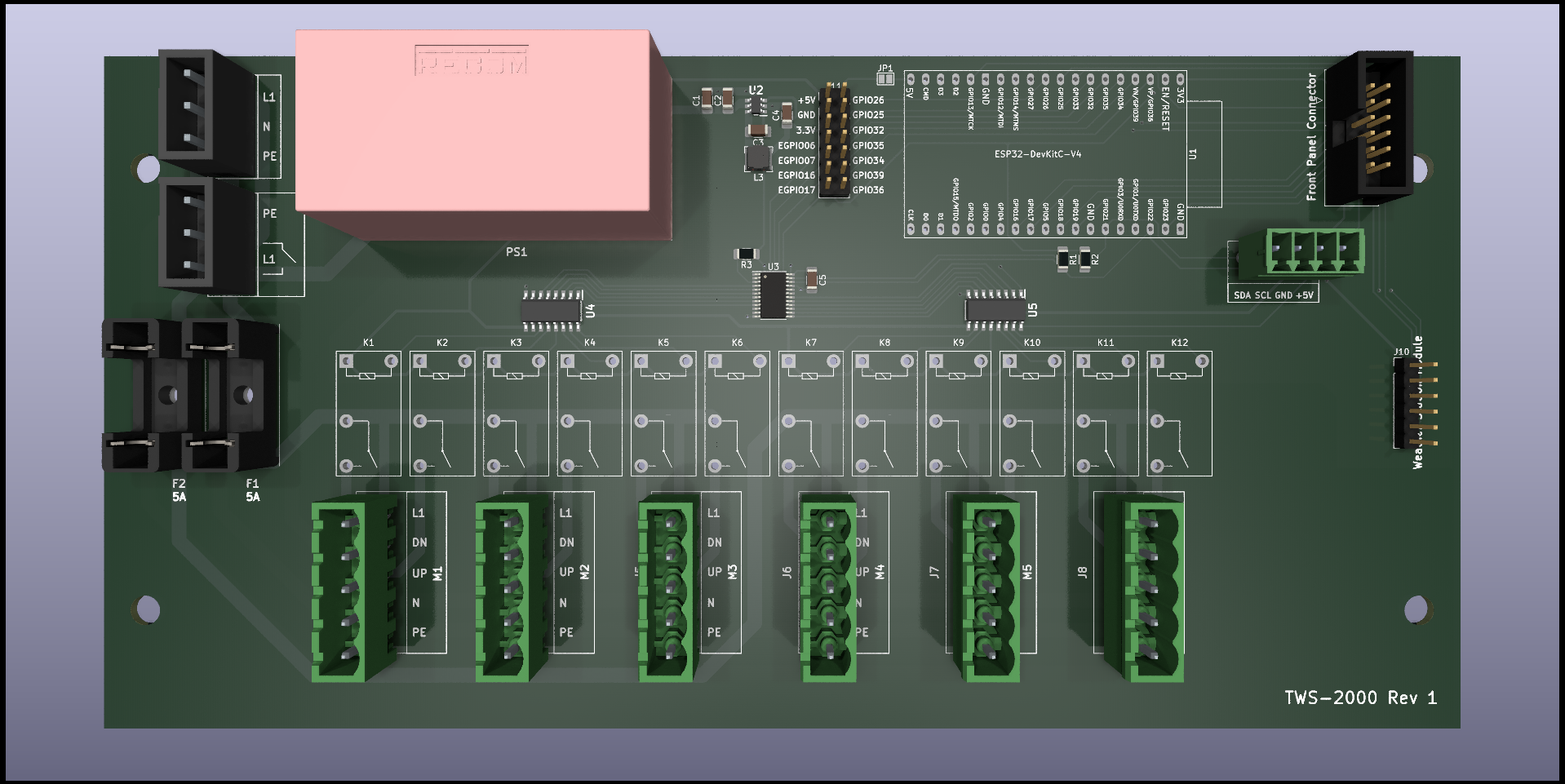
3D render from front (no 3D model for relays K** and MCU board; 3D model for J1 and J2 is a stand-in of same outer dimensions):
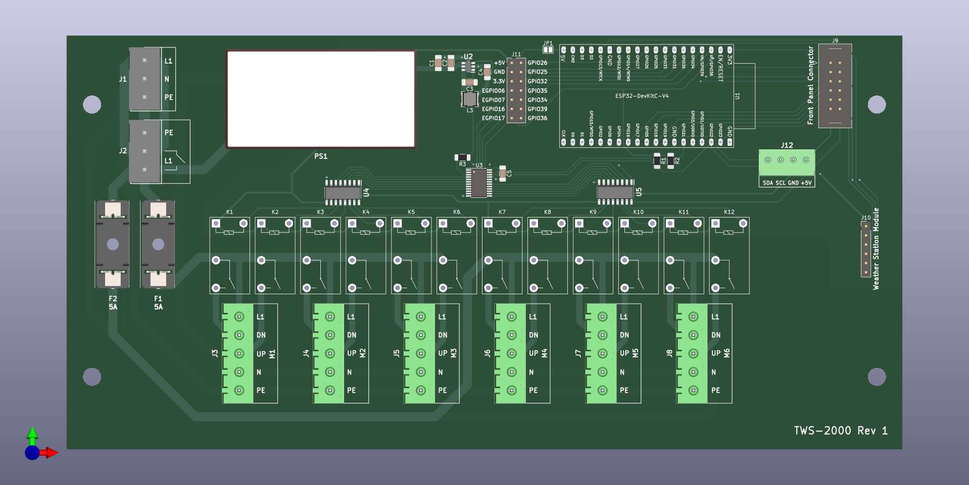
Orthographic view from front:
Schematic:
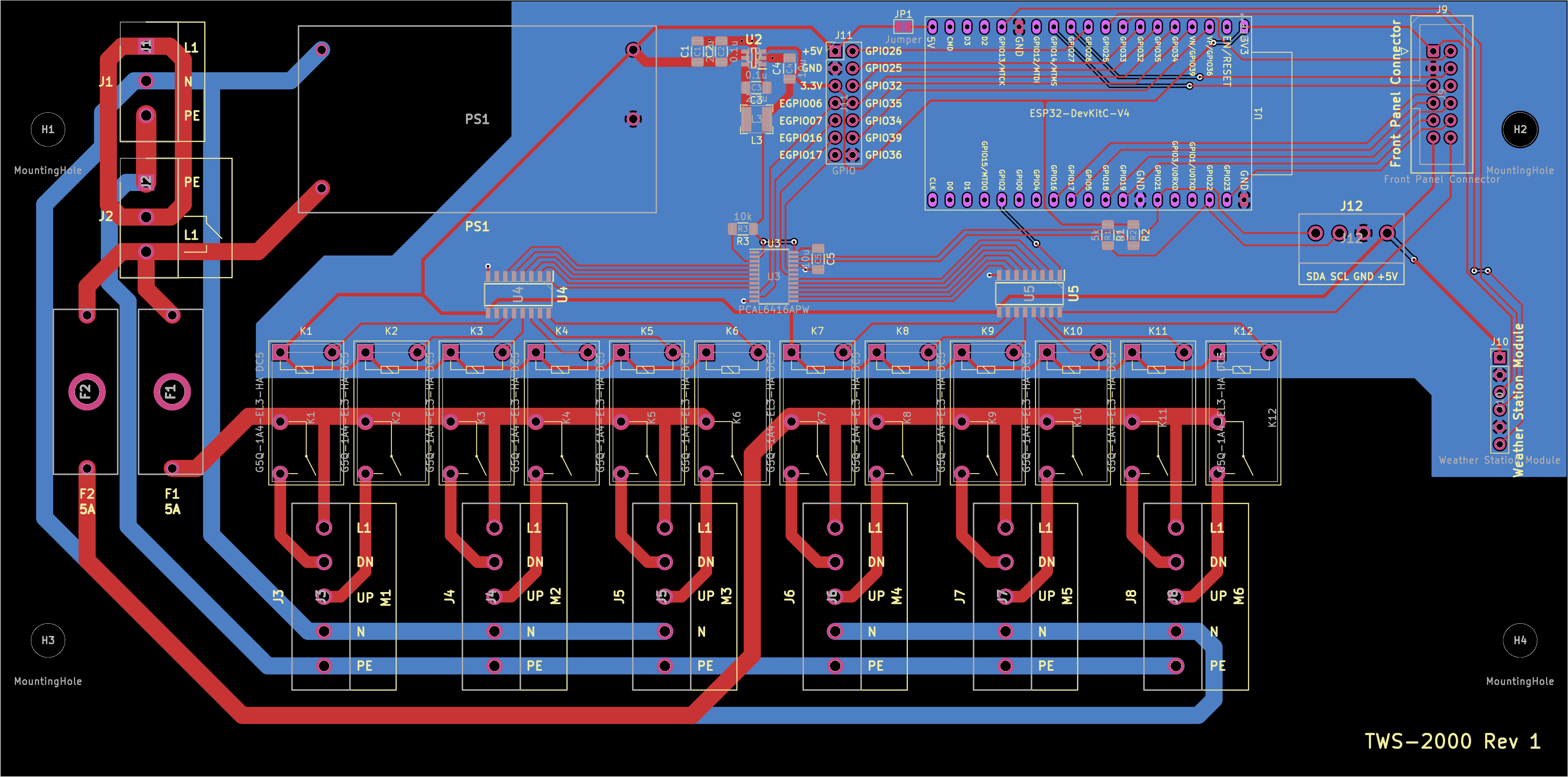
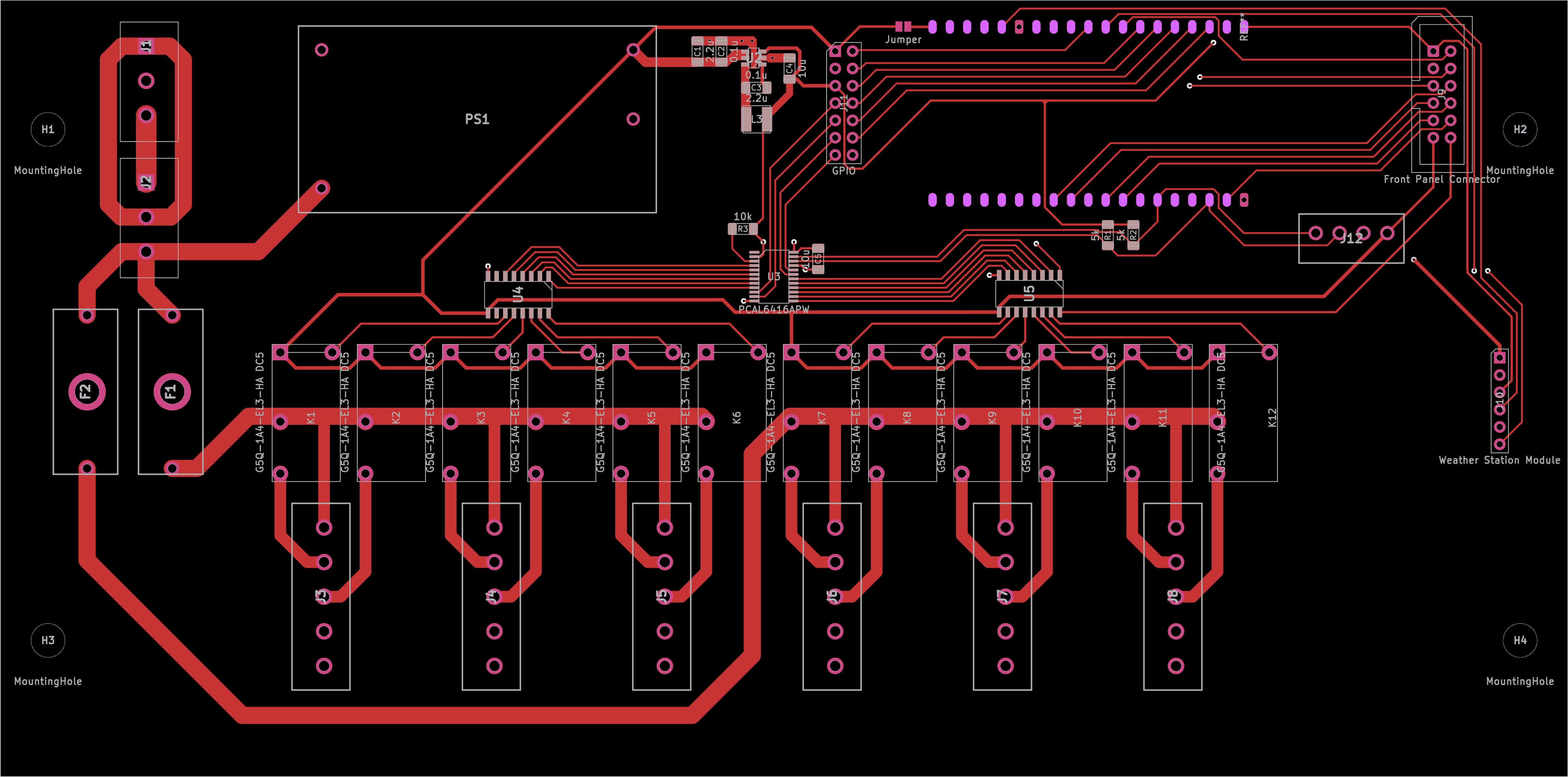
PCB All layers (For reference: thickest traces are 2.5 mm / ~98.4 mils; thinnest traces are 0.25 mm / ~9.84 mils):
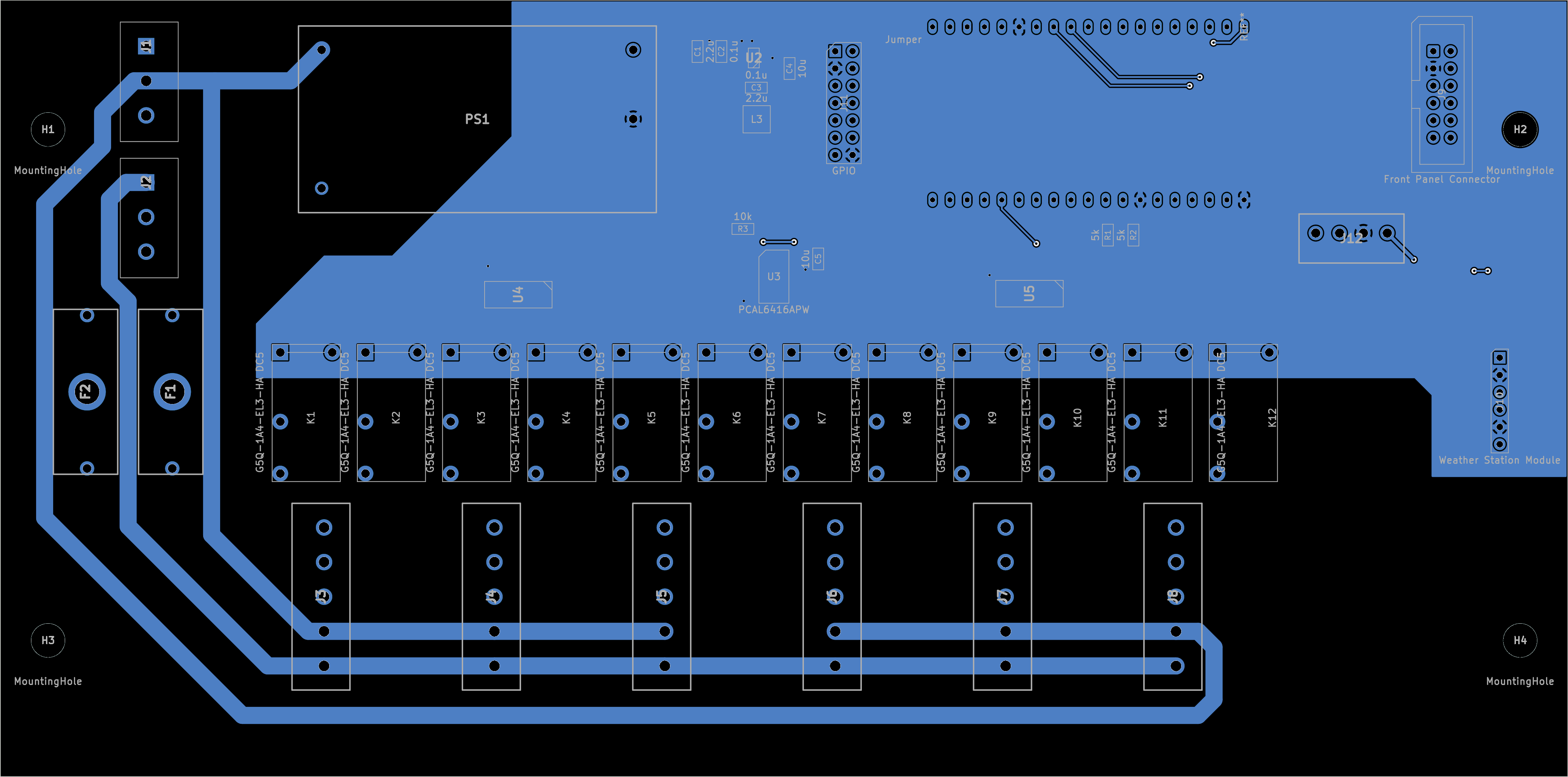
PCB Front layers excluding Silkscreen:
PCB Back layers + Front Fab layer:
view more: next ›
I have never used them but there are some tools that advertise being able to run GitHub Actions locally, like WRKFLW.